Injection molding is a widely used manufacturing process for producing plastic parts with high precision and efficiency. One of the most critical factors in designing injection molded parts is determining the appropriate injection molding wall thickness.
Proper wall thickness ensures structural integrity, minimizes defects like sink marks and warpage, and optimizes material usage and cycle time.
This tutorial explores key considerations and best practices for achieving uniform and optimal wall thickness in plastic injection molding projects.
The Basics of Injection Molding Wall Thickness
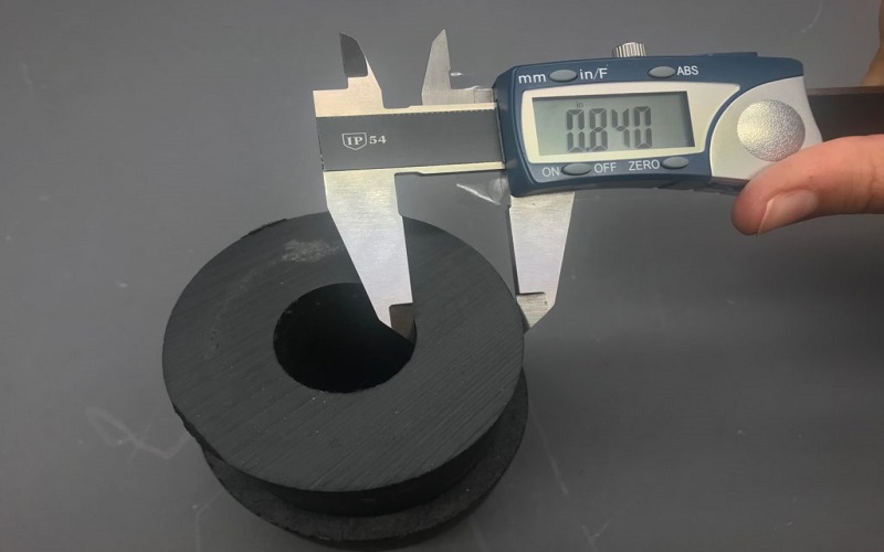
Injection molding wall thickness refers to the thickness value between the outer and inner walls of a plastic part, which is equivalent to the cavity thickness in the mold.
It is one of the most important structural parameters in injection molded product design, directly affecting the flow, cooling, shrinkage of molten plastic, as well as the final part quality, cost, and production efficiency.
A general rule in injection molding is to maintain uniform wall thickness throughout the part wherever possible. This helps to avoid sharp internal corners and long unsupported spans that can lead to stress concentrations and warpage.
When variations in wall thickness are necessary due to functional or aesthetic reasons, transitions should be gradual, using fillets or chamfers to modify wall thicknesses smoothly and reduce the risk of other defects.
Thicker areas in a part can increase cooling time significantly, as cooling time increases with the square of the wall thickness. Excessively thick walls, generally recommended to be kept below 5 mm, can also cause internal porosity and sink marks due to uneven shrinkage.
Conversely, thin areas might be prone to incomplete filling or weak mechanical strength if the material flow is insufficient.
In summary, understanding and applying the principles of injection molding wall thickness are essential for producing high-quality, cost-effective plastic parts with minimal defects.
The Significance of Consistent Wall Thickness In Injection Molding
Maintaining a consistent wall thickness throughout an injection molded part is vital for ensuring a smooth and predictable flow of molten plastic material during the injection molding process.
Uniform wall thickness helps minimize variations in material flow behavior and cooling rates, which directly impacts the part’s dimensional accuracy and structural integrity.
When walls vary significantly in thickness—referred to as non uniform wall thickness—issues such as internal stresses, warpage, sink marks, and other part defects are more likely to occur.
A good rule of thumb in injection molded plastics design is to keep the thickness of adjacent walls within 40% to 60% of the nominal wall thickness to avoid abrupt transitions that create stress concentrations and disrupt mold flow.
Abrupt thickness changes can cause trapped air and increase shear stress in the molten plastic, leading to cosmetic defects and short shots where the mold cavity is not fully filled.
Thick walls or thick sections cool more slowly than thin walls, resulting in longer cycle times and potential warpage due to uneven shrinkage. Conversely, thin walls require higher material flow rates and can be prone to incomplete filling or weak mechanical properties.
This delicate balance between thin walls and thick walls must be carefully managed during the design phase to optimize part strength, manufacturability, and cost.
How To Select The Optimal Injection Molding Wall Thickness?
Selecting the optimal injection molding wall thickness is a critical step in achieving high-quality, cost-effective plastic parts. The ideal wall thickness balances material flow, cooling time, structural strength, and manufacturing efficiency.
For most applications, a general wall thickness range of 1.2mm to 3mm is a good starting point, with a recommendation to keep wall thickness below 5mm whenever possible.
Selecting the appropriate plastic material is equally important because the flow characteristics, shrinkage rates, and mechanical properties vary among different plastics. Therefore, wall thickness design needs to be optimized in conjunction with material selection.
Although the optimal wall thickness varies depending on specific strength and performance requirements, below is a general reference table of recommended wall thicknesses for common plastics:
Plastic Material | Recommended Wall Thickness (mm) |
|---|---|
Acrylonitrile Butadiene Styrene (ABS) | 1.2 – 3.0 |
Polycarbonate (PC) | 1.0 – 3.5 |
Polypropylene (PP) | 1.0 – 3.0 |
Polyethylene (PE) | 1.0 – 3.0 |
Polystyrene (PS) | 1.0 – 3.0 |
Nylon (PA) | 1.0 – 3.5 |
Polyethylene Terephthalate (PET) | 1.2 – 3.0 |
Thermoplastic Elastomers (TPE) | 1.0 – 3.0 |
What Is The Maximum Wall Thickness For Injection Molding ?
Excessively thick walls, typically those over 5 mm, can lead to defects such as internal porosity and sink marks due to uneven cooling and shrinkage. Thicker sections also increase cycle times significantly since cooling time increases with the square of the wall thickness.
This not only affects production efficiency but can also cause part warpage due to differential shrinkage rates. Therefore, keeping wall thickness under 5 mm is generally advised unless specific design requirements necessitate otherwise.
What Is The Minimum Wall Thickness For Injection Molding?
Walls that are too thin can create challenges during molding, including incomplete filling or short shots, resulting in fragile parts with insufficient mechanical strength.
Thin walls require higher-flow materials and precise processing parameters to ensure complete mold filling, which is especially relevant in thin wall injection molding.
While the minimum wall thickness varies by material, it is often around 1 mm for many plastics, though some materials and designs may allow thinner sections.
Design Tips For Wall thickness In Injection Molded Parts
Wall thickness is one of the most fundamental considerations in part design. Reasonable wall thickness design is key to ensuring part quality and manufacturing efficiency.
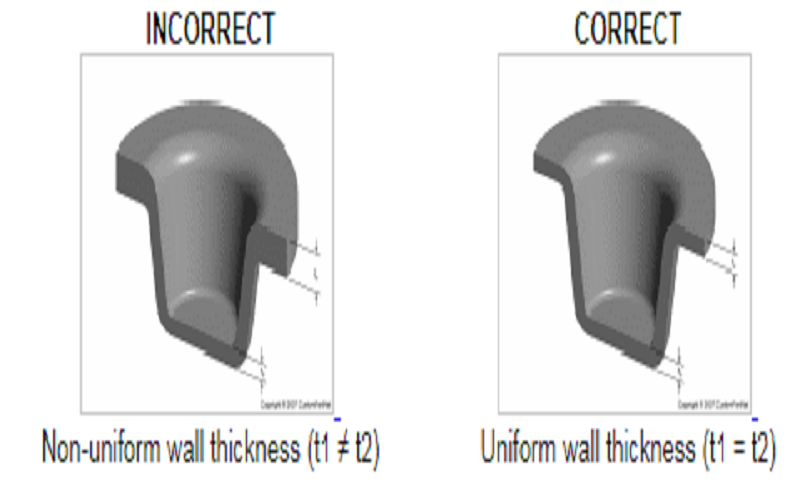
Uniform Wall Thickness
The most important principle in injection molding wall thickness design is to maintain uniform wall thickness.
Uniform wall thickness is crucial in injection molding as it allows for consistent flow and cooling of molten plastic, minimizing internal stresses that can lead to defects such as warping and sink marks.
Non-uniform thickness leads to inconsistent melt flow and large differences in cooling rates, causing uneven shrinkage and concentrated internal stresses, which ultimately result in sink marks, warpage, or cracking.
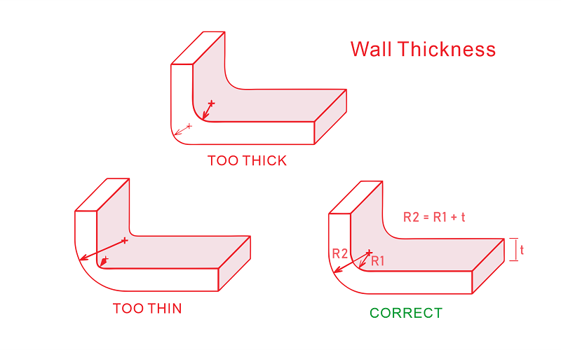
Gradual Thickness Transitions
Changes in wall thickness should be designed with gradual transitions, using fillets or chamfers to avoid sharp corners and abrupt changes, reducing flow inconsistencies and cooling differences during injection molding.
Rib Design
Additionally, ribs should be reasonably utilized in the design to enhance strength. The rib thickness is typically 40% to 60% of the nominal wall thickness or outer wall thickness, adhering to the recommended thickness guidelines.
The rib height should not exceed three times the main wall thickness, and appropriate draft angles and radii should be designed to ensure smooth flow and easy demolding.
Boss Design
Bosses, commonly used for screw fastening or assembly positioning, also require careful wall thickness design, recommended to be 40%-60% of the nominal surrounding wall thickness. The root of the boss should have a smooth transition with the main wall, and ribs should be added to distribute stress and avoid local sink marks.
Draft Angle Settings
Draft angles are fundamental for successful demolding of injection molded parts. Vertical surfaces require at least 0.5° to 2° draft angle.
For every 0.25 mm increase in wall thickness, it is recommended to add an additional 1° to 1.5° draft angle. Textured surfaces (with grain patterns) require larger draft angles, typically 3° to 5° or more.
Gate and Flow Path Design
Finally, reasonable gate placement and flow path design are crucial to ensure uniform filling of the molten plastic. Gates should be positioned in thicker wall areas to maintain an open flow path and prevent premature solidification in thinner areas that could cause incomplete filling.
Flow analysis and other design tools can be used to identify potential flow and cooling issues early and optimize the design accordingly.
In summary, injection molding wall thickness design requires comprehensive consideration of material selection, structural reinforcement, flow path, and manufacturing processes to achieve high-quality and efficient production.
Common Defects Caused By Bad Wall Thickness Design
In the injection molding process, improper wall thickness design is one of the main causes of part quality issues. Common defects include sink marks, warpage, short shots, voids, and surface imperfections.
These problems not only affect the appearance and performance of parts but can also lead to reduced production efficiency and increased costs. Reasonable design considerations and process adjustments are essential to address these defects.
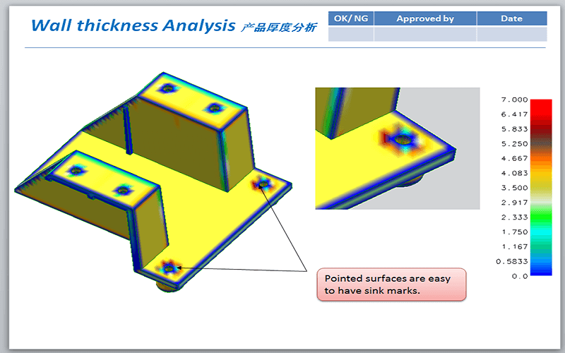
Sink Marks
Sink marks are depressions formed due to uneven cooling caused by excessively thick walls and inconsistent internal material shrinkage.
Solutions include maintaining uniform wall thickness, avoiding locally thick areas, using rib structures instead of thickening walls, and optimizing cooling system design to accelerate cooling in thick sections.
Warpage
Warpage is usually caused by uneven wall thickness leading to differential cooling rates and internal stress accumulation.
During design, ensure gradual wall thickness transitions, avoid abrupt thickness changes, properly arrange ribs and reinforcing structures, and combine appropriate mold temperature control and injection molding process parameter adjustments to reduce warpage risk.
Short Shots
Short shots occur when molten plastic fails to completely fill the mold cavity due to excessively thin walls or improper runner design.
Selecting suitable materials and reasonable wall thickness ranges, optimizing runner and gate locations, and ensuring smooth molten material flow throughout the mold are necessary.
Voids
Voids are often caused by large wall thickness variations or poor venting, where gases cannot escape timely during molten plastic flow. Design should avoid abrupt wall thickness changes, add venting grooves, or adjust gate positions appropriately to ensure gas is properly vented.
Surface Defects
Surface defects such as flow lines and uneven textures are often related to non-uniform wall thickness and uneven cooling. Maintaining uniform wall thickness, optimizing mold surface treatment, and cooling system design can effectively improve surface quality.
Conclusion
In conclusion, proper injection molding wall thickness design is essential for producing high-quality, cost-effective plastic parts.
Maintaining uniform wall thickness and gradual transitions minimizes defects such as warpage, sink marks, and short shots, while optimizing material flow and cooling efficiency.
Selecting the appropriate wall thickness in combination with the selected material and incorporating design features like ribs and bosses can enhance part strength without unnecessary thickness.
Careful consideration of draft angles, gate placement, and flow paths further supports manufacturability and part performance.
By following these best practices, manufacturers can achieve consistent, reliable injection molded parts that meet both functional and aesthetic requirements.