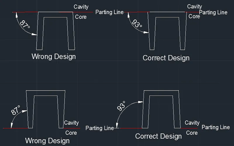
In previous articles on draft angles, we discussed the need for draft angles to remove injection molded parts from the mold. However, the prerequisite is that the mold must first be split.
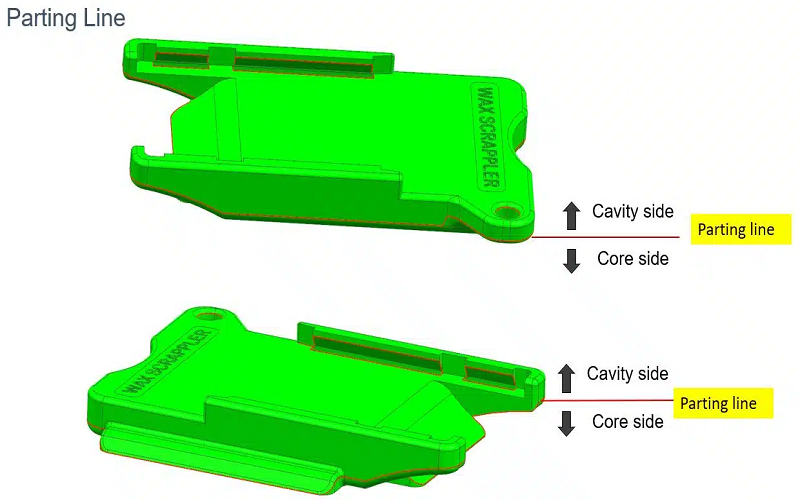
The parting line is directly related to the mold separation process. It marks the junction where the upper and lower halves of the mold meet when closed.
Proper parting line design affects demolding, surface quality, and mold lifespan.
In the following sections, we will delve into the design principles, common issues, and optimization strategies for injection molding parting line, helping you better understand the importance of this key factor in the injection molding process.
What Is The Parting Line In Injection Molding?
The parting process refers to dividing the core part of the molded plastic component into several modules, with the contact surfaces between these modules called the parting faces, also known as mold separation faces.
The boundary line where the parting face intersects the surface of the plastic part is called the parting line.
Since it is impossible to achieve a perfectly seamless contact between the molding modules, any small gap between them will be replicated on the plastic part, leaving a residue similar to a flash, which appears as a line and is thus called the parting line.
In simple terms, the parting line is the physical boundary formed between the two parts of the mold during the injection molding process.
Basic Forms Of Injection Molding Parting Line
Depending on the mold structure and design requirements, the different types of injection molding parting lines are as follows:
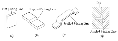
Flat Parting Line
This is the most common form of parting line, typically perpendicular to the opening direction of the mold.
The mold structure is simple, but the parting line area is prone to sharp edges, which may cause injury.
It usually needs to be used with other components, and a stop or decorative groove is added between the mating parts to prevent step differences.
Stepped Parting Line
In some cases, to improve injection efficiency or the demolding performance of the plastic part, the parting face is designed as a stepped shape. This helps balance injection eccentricity and makes the mold structure more compact.
If the step difference is too large, pillow blocks can be considered, or a local stepped parting face can be designed.
Slanted Parting Line
This type of parting line is suitable for plastic parts that require lateral core pulling.
Slanted parting lines help simplify the mold structure, but attention must be paid to the angle to prevent wear on the mold during use.
Curved Parting Line
Curved parting lines are typically used for parts with complex shapes.
They can form the plastic part through a complex mold design, but this also increases the difficulty of mold processing.
Each of these parting line types has its own characteristics and should be selected based on the specific molding requirements and mold structure.
Why Parting Line Location Matters in Injection Molding?
In the injection molding process, the parting line is a crucial factor, as its position directly affects the product’s appearance, mold design complexity, and the ease of demolding and processing.
Product Appearance
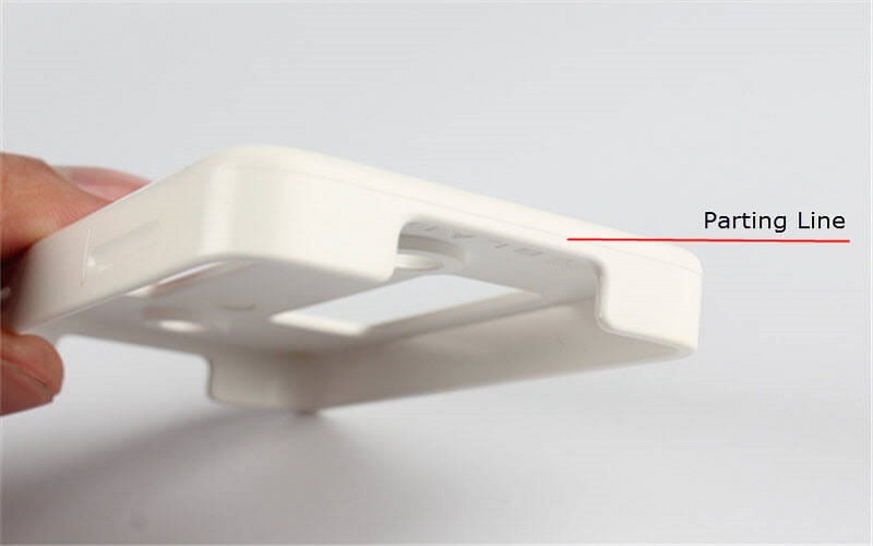
The position of the parting line directly impacts the surface quality of the molded part, as it leaves a visible seam.
To minimize its effect on appearance, the parting line is usually placed in less conspicuous areas.
If unavoidable, techniques such as texturing can be used to reduce the visibility of the parting line.
Mold Design
The location of the parting line influences the complexity of the mold structure.
For parts with high aesthetic requirements, the parting line should be avoided in visible or prominent areas.
If this is not possible, careful mold design and techniques can be applied to minimize its visual impact.
Demolding and Processing
Parting lines are typically placed at the edges or highest points of the part, making demolding easier and more aesthetically pleasing.
Additionally, the parting face should be designed in a way that facilitates processing, prioritizing flat parting faces, followed by slanted parting faces, and lastly, curved parting faces, to simplify manufacturing and improve efficiency.
Proper placement of the parting line can enhance both the appearance and manufacturability of the product, striking a balance between product performance and production costs.
How To Define Parting Line?
When determining the parting line, the shape and position on the plastic part need to be defined first.
Once the mold opening direction is set, locating the parting line becomes easier, as its projection in this direction matches the outer contour of the part.
A straight line parallel to the opening direction is moved along the part’s outer contour to find intersection points.
In two color injection molding, the parting line location also depends on design, aesthetics, processing feasibility, and material flow.
The following scenarios apply:
- If the line intersects at a single point, that point is on the parting line.
- If the line intersects at a segment, any point on the segment can be on the parting line, usually choosing the point closest to its adjacent point.
- If the line intersects at multiple points or segments, core pulling may be required, and the parting line should be based on the core pull’s shape and size.
In summary, parting line positioning should consider the part’s shape, mold opening direction, and other process factors.
Methods To Optimize Parting Lines
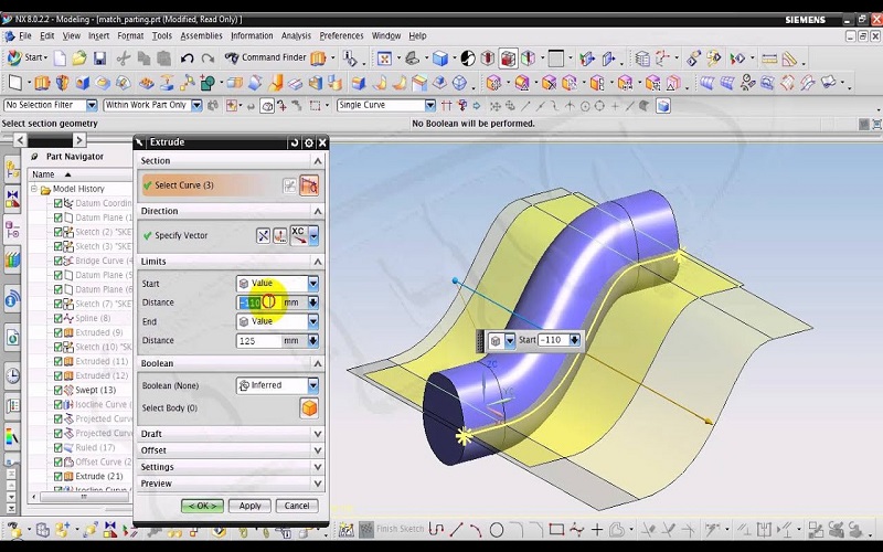
In the UG modeling module, first extract the parting line of the product, then use the extrusion command to stretch the parting line and form the parting surface.
If the parting surface is not smooth, it can be optimized by connecting broken line segments and using bridge curves.
For parting lines at the edges or turning points of the product, direct extrusion may cause the parting surface to bend or wrinkle.
To optimize the parting surface, methods such as changing the extrusion direction, using bridge curves, and applying mesh surfaces can be used to make the surface smooth, aesthetically pleasing, and easy to process.
Conclusion
In conclusion, the parting line is crucial in injection molding, affecting both the quality and aesthetics of molded parts.
By optimizing parting line design, injection molding manufacturers can improve product precision, strength, and appearance.
With over 40 years of experience, FOWMOULD ensures the highest quality and efficiency in parting line design and mold optimization.
We help you meet exact specifications while minimizing costs.
For assistance, send us your 2D/3D drawings, and our team will provide professional advice and design recommendations.