Injection molding is a widely used manufacturing process for producing precise plastic parts in large volumes.
At the heart of this process lies the injection molding core and cavity, the critical components of a mold that define the shape and features of the final product.
This article explores the roles, design, and interaction of the core and cavity, providing a clear understanding of their importance in injection molding.
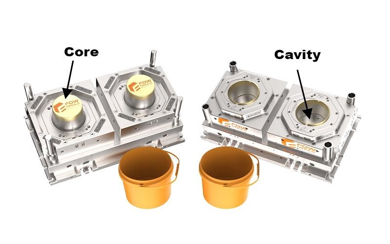
What Are Core and Cavity in Injection Molding?
These two components come together in the mold assembly to create the shape and internal features of the final product.
The mold core is the movable component that shapes the internal features of the part. They are typically machined from hardened steel and remain fixed in the mold throughout the production process.
Complex core designs may include features like slides, lifters, or collapsible cores to accommodate undercuts and facilitate part release.
Conversely, the mold cavity is responsible for forming the external shape of the product. This hollow mold structure matches the external geometry of the desired part, providing the space that the molten plastic fills to form the part’s outer surface.
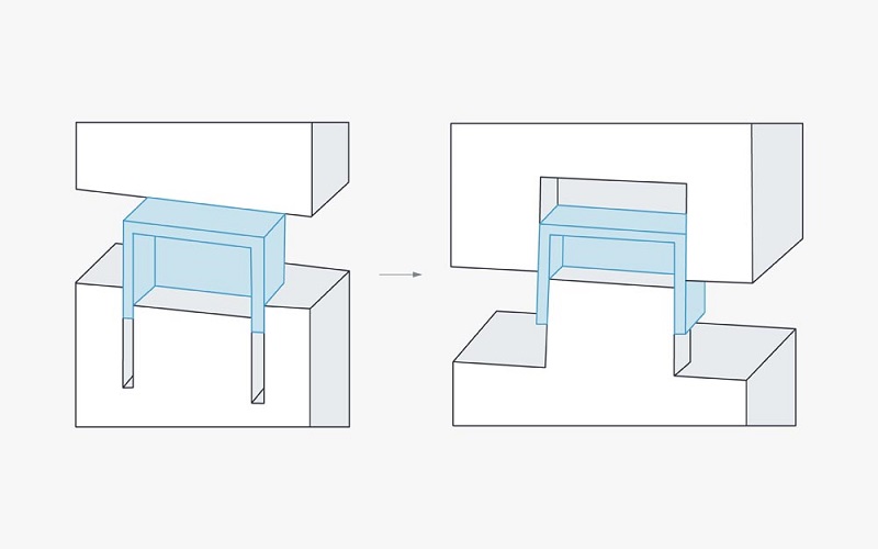
The interplay between the core and cavity is crucial. When the mold closes, the core and cavity align precisely, ensuring that the molten plastic fills the entire mold without defects.
This precise alignment is vital to prevent issues like flash or warping, which can compromise the quality of the molded part.
Throughout the injection molding process, the mold repeatedly opens and closes, subjecting the core and cavity to significant stress and requiring that the two plate mold requires them to maintain tight tolerances.
Their proper design, construction, and maintenance are vital for achieving consistent and high-quality injection molded products.
This intricate dance between the core and cavity underpins the entire injection molding process, highlighting their indispensable role in manufacturing, including the intricate details of the molding process.
The Importance of Core and Cavity in Injection Molding
The mold core and cavity are fundamental components in injection molding, working together to shape the final product with precision and efficiency. Their design and placement critically impact the quality, dimensional accuracy, and production efficiency of the molded parts.
Proper core and cavity placement ensure that the product meets its intended specifications while maintaining high production rates and minimizing defects.
The Role of the Core in Injection Molding
The mold core is responsible for sculpting the molded part’s internal features, such as intricate details, hollow portions, and complex geometries. It directly impacts the end product’s correctness, functionality, and quality.
For instance, in plastic pipe fittings, the core defines the inner diameter and internal structural features, ensuring the fitting meets various usage requirements.
Additionally,the core is quite strong and thick as it undergoes molding pressure during its construction. It usually has built-in features like cooling and ejection pins. two halves
This is particularly crucial for large injection molded plastic products, where the core’s strength and rigidity are essential to prevent deformation or damage.
The Role of the Cavity in Injection Molding
The mold cavity primarily shapes the external contours and appearance of the product. It is the main space that the molten plastic fills, defining the overall desired shape, size, and surface features of the final product.
For example, in manufacturing mobile phone cases, the cavity’s precise shape and surface quality directly influence the case’s smoothness, glossiness, and dimensional accuracy, thus affecting the product’s overall quality and market competitiveness.
Moreover, the cavity’s design controls the flow of molten plastic, ensuring uniform filling to avoid defects such as flow marks, air bubbles, or incomplete filling.
By incorporating features like runners and gates, the cavity guides the plastic flow along predetermined paths, enhancing the overall molding quality.
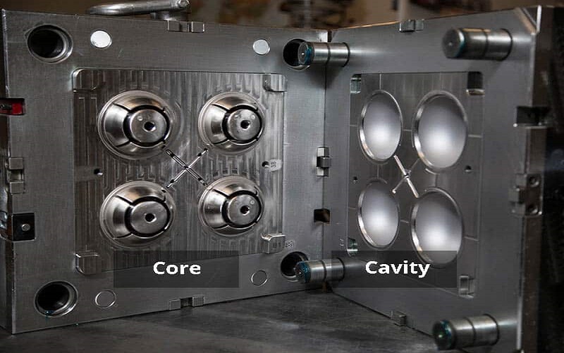
How To Distinguish Core and Cavity in Injection Molding?
In injection molding, distinguishing between the mold core and the mold cavity is primarily based on their functions, appearance, and structural characteristics within the mold.
molten plastic is injected during the process. The core portion is responsible for providing the internal surface, whereas the cavity forms the exterior surface.
Examine the Part Geometry
Look at the molded part and identify its internal and external surfaces. The internal features (e.g., holes, threads) are shaped by the core, while the external surfaces (e.g., outer walls, textures) are shaped by the cavity.
Check the Mold Design
In a mold diagram or physical mold, the core is the protruding component, and the cavity is the recessed counterpart. CAD models or mold blueprints clearly label these components.
Consider Part Ejection
The core is often on the ejector side of the mold, as it helps push the part out after cooling. The cavity, on the stationary side, typically remains fixed during ejection process.
Markings and Others
Cores and cavities are usually identified using numbers or marks. For example, ejection pin marks identify the core side.
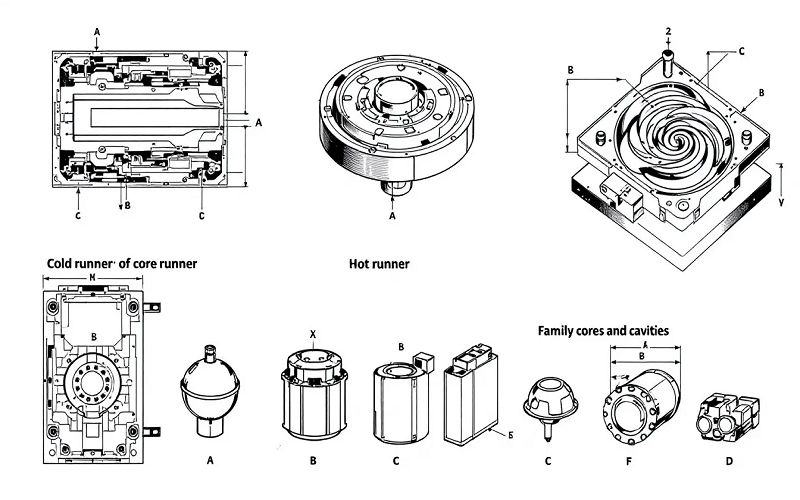
Types of Core and Cavity for Injection Molding
In injection molding, cores and cavities are categorized based on various criteria that influence production efficiency and part characteristics. Understanding these types helps in selecting the appropriate mold design for specific production needs.
1. Based on Number of Impressions (How many parts are made per cycle):
Single Cavity Mold
A single cavity mold contains only one core and cavity set, producing one part per injection cycle. This is common for large parts, low production volumes, or highly complex parts where consistency is paramount.
The primary advantages are simpler tooling and lower initial mold costs, though the production output is lower.
Multi-Cavity Mold
In contrast, a multi-cavity mold contains multiple identical core and cavity sets within the same mold base, producing several identical parts per cycle.
This type is ideal for high-volume production of smaller parts, offering high production output and lower cost per part. However, it involves higher initial mold costs and more complex design.
Family Mold
Family molds contain multiple different core and cavity sets within the same complete mold base, typically for mold parts that are assembled together or belong to the same product line.
This design reduces the number of three plate molds needed and ensures all parts of an assembly are molded simultaneously. However, balancing fill, pressure, and cooling for different geometries is challenging, potentially leading to compromises in part quality or cycle time.
2. Based on Construction Method:
Solid (Monolithic) Core/Cavity
Solid (monolithic) cores and cavities are machined directly from a single, solid block of tool steel or aluminum, providing high strength and durability for straightforward designs.
While they offer fewer potential leak paths and good thermal conductivity, they can be expensive and difficult to machine for complex features.
Inserted Core/Cavity
Inserted cores and cavities involve machining pockets into the main core/cavity block and fitting separate pieces of steel (threaded inserts) into these pockets.
This method is common for complex parts or those requiring different surface finishes/materials in specific areas. It allows for easier machining of complex details, use of specialized materials, and simple replacement of damaged inserts. However, precise fitting is necessary to avoid flash or movement.
Laminated Core/Cavity
Laminated cores and cavities are constructed from thin, precisely machined two plate cavity plate bonded together to create complex features.
This method enables the creation of geometries that are impossible with other methods and is used for intricate conformal cooling channels. Despite their advantages, they are complex and expensive to design and manufacture, with potential for leakage or delamination.
3. Based on Features Requiring Special Actions :
Straight Pull Core/Cavity:
Design: The part features allow it to be ejected directly along the mold opening direction without any obstruction. No undercuts perpendicular to the line of draw.
Use: Simpler parts.
Core/Cavity with Side Actions (Slides/Cams):
Design: Incorporate moving components (slides) within the mold, often actuated by angle pins or hydraulic/pneumatic cylinders. These slides contain core or cavity features themselves.
Use: To form external undercuts, holes, or features on the sides of the part that are not in the line of draw. The slides retract before ejection.
Core/Cavity with Lifters:
Design: Incorporate mechanisms (lifters) typically mounted on the ejection system. They move with the ejector plate but also travel at an angle.
Use: To form internal undercuts or features that cannot be formed by the main core/cavity or slides. The lifter moves inwards/sideways as it pushes the part off the core.
Unscrewing Cavities and Cores
Design:The core (or sometimes cavity inserts) is designed to rotate, driven by hydraulic motors, servo motors, or rack-and-pinion systems.
Use: To mold and release parts with internal or external threads.
Material Selection for Mold Core and Cavity
Material selection for mold cores and cavities significantly impacts the mold’s longevity, cost, and performance.
Factors such as thermal conductivity, durability, wear resistance, and material characteristics are crucial in choosing the right materials. Typically, cores are made from cast iron, steel, or alloys, while cavities often use tool or alloy steel.
The choice of material must balance lifespan, cost, and production demands to ensure optimal performance in the injection molding process.
Aluminum
Aluminum alloys are favored for their ability to cool faster during the injection molding process, which reduces cycle times and enhances production efficiency.
However, aluminum has poor strength and wear resistance compared to steel, making it less suitable for high-pressure molding applications. This limitation is particularly significant in mass production scenarios where durability is crucial.
Hardened Steel
Hardened steel is a wear resistant materials preferred for molds . Steel alloys offer the durability needed for high-volume production, ensuring the mold can withstand repeated use without degrading.
This material choice is ideal for scenarios where the mold must maintain its precision and integrity over thousands of cycles.
Copper and Beryllium Alloys
Beryllium-copper alloys are highly valued in high-temperature applications due to their excellent thermal conductivity.
These alloys help manage the heat generated during the injection process, ensuring consistent cooling and reducing the risk of warping or defects in the final product through heat treatment.
Their unique properties make them suitable for specialized mold components that require efficient heat dissipation.
How To Choose Core and Cavity Placement In Injection Molding?
Choosing the placement of the core and cavity in injection molding is a critical step that influences part quality, mold functionality, production efficiency, and overall cost.
The injection mold core and cavity placement determines how the internal (core-formed) and external (cavity-formed) features of a part are shaped, how the part is ejected, and how the mold operates.
Parting Line Placement
The parting line is where the core and cavity meet when the mold closes. It should be positioned to avoid critical areas (e.g., visible surfaces, sealing edges) and align with the part’s natural geometry.
A well-placed parting line minimizes flash (excess material) and ensures easy mold separation.
Ejection and Demolding
The core is typically placed on the moving side (ejector side) of the mold, as it integrates with the ejection system (e.g., ejector pins or sleeves) to release the part after cooling. Parts often shrink onto the core, making this placement ideal for demolding.
To ensure that the part stays in the mold half with the ejector system, we would design the mold so that the outside of the glass is formed in the cavity of the mold (A-side) and the inside would be formed by the core of the mold (B-side).
Ensure sufficient draft angles (tapered walls) on both core and cavity to facilitate part release without damage.
Material Flow and Gate Placement
The cavity is often placed on the stationary side, near the sprue or gate, where molten plastic enters the mold. This ensures efficient filling of the external surfaces.
Gate placement should avoid visible or functional areas of the part. For example, gates are often located in non-aesthetic areas formed by the cavity to minimize surface defects like flow marks.
Calculation Of The Cavity Size
The cavity size is calculated by adjusting the nominal part dimensions to account for shrinkage and other factors. The basic formula is:
Cavity Dimension = Part Dimension × (1 + Shrinkage Rate)
Where:
Part Dimension: The final desired dimension of the molded part (e.g., length, width, height).
Shrinkage Rate: The material’s shrinkage factor (e.g., 0.005 for 0.5% shrinkage).
For more precise calculations, additional adjustments may be made for mold tolerances, thermal expansion, and processing variations:
Cavity Dimension = Part Dimension × (1 + Shrinkage Rate) + Mold Tolerance Adjustment
Summary
In summary, the core and cavity are vital components in the injection molding process, defining the internal and external features of molded parts.
Their design and material selection are crucial for maintaining quality, efficiency, and production rates. By understanding and optimizing these elements, manufacturers can achieve superior results, reducing cycle times and improving the surface quality of their products.
Proper core and cavity is the cornerstone of successful injection molding, ensuring high quality products and efficient production.